|
It’s dark at night. Photographs of stars require longer exposures.
Because the earth is rotating, a star’s position will change
during a long exposure, slowly drifting from east to west. To
avoid getting a blurred picture (star trails), the camera must
track the star’s apparent movement while the lens is open.
To accomplish this the camera can be attached to a simple device
called a Barn Door Tracker which keeps the camera pointed
at the stars as they appear to move. I was inspired to build a
Barn Door Tracker by an article in Telescope Making
magazine by
Gary Seronik. The basic idea is that the camera is attached
to a platform that rotates at the same rate as the earth rotates.
If all the dimensions are correct, and the board's axis of rotation
is parallel to the earth's, the camera will track the apparent
movement of the stars.
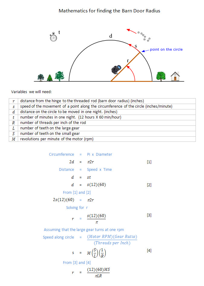
The purpose of this page is to show how to calculate the proper
dimensions.
|
|
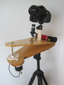
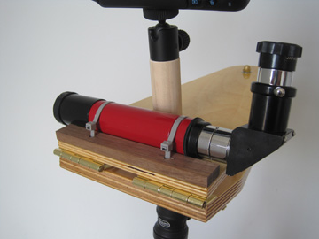
Pictured here is my Barn Door Tracker. The bottom board is stationary.
The top board is hinged to the bottom board and driven upward
by a threaded rod.
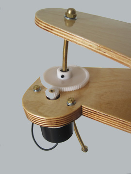
The larger gear is threaded onto the rod and driven by the smaller
gear attached to a motor. As the large gear turns, it drives
the rod upward. The rod is curved to match the radius of curvature
as the top board swings open.
|
|
|
|
The motor is powered by a 9 volt battery and an adjustable voltage
regulator. The voltage can be adjusted so that the rate at which
the top board raises matches the rate that the stars appear
to move across the sky
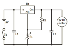
C1 - 0.1 mfd capacitor
C2 - 0.1 mfd capacitor
R1 - 500 ohm potentiometer
R2 - 150 ohm resistor
U1 - LM-317T adjustable regulator
|
|
|
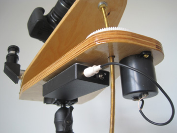
The axis of rotation of the board must be parallel to the earth's.
This is accomplished by pointing the hinged edge of the board
at the north celestial pole (at the star, Polaris). A small
finder scope helps with this alignment.
The camera is attached to the top board with a ball head mount
so it can be pointed at any part of the sky.
|
|
|
|
|
The design calls for the larger gear to rotate once per minute.
A black spot on the gear will help measure the time of
one revolution. Using the variable resistor in the voltage regulator
circuit you can fine tune the speed at which gear rotates.
|
|
|
The critical dimensions are: the RPM of the motor
(M),
the number of teeth on the small and large gears
(S
and L), the threads/inch of the rod
(R), and the distance from the center
of the hinge pins to the center of the rod (Barn Door Radius).
All dimensions except the Barn Door Radius are limited
to what you can find to buy. The calculator at the right will
find the proper Barn Door Radius given any combination
of the other dimensions. The initial dimensions are the ones
used for the Barn Door Tracker pictured above.
|
|
|
|
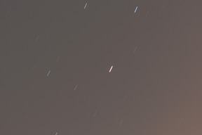
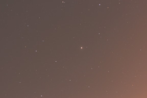
Both of these images are of the same part of the sky, and each
was exposed for 4 minutes.
The one on the left was made with the Barn Door Tracker
turned off. The star trails are evident.
The Barn Door Tracker was turned on during the exposure
on the right. Cool!
|
|
|